
IVR Tutorial Lesson 1: Call Flow Diagram
The design so far:
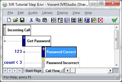
As you can see, the IVR application is defined as a tree structure similar to the way folders and files are structured in Windows. This tree structure is called a call flow diagram. A call flow diagram looks like the user manual of a voicemail system.
The tree node is called an element in IVR Studio. An element defines a certain stage of an IVR application. For example, the Get Password element starts right after an incoming call is answered. An element also defines a set of prompt items and activities. As an example, the Get Password element plays the welcome message and waits for the caller to enter his or her password.
The link between elements is called a transition. A transition defines a change of the active element. In order for a transition to happen, the condition for the transition must be satisfied. For example, the transition from Get Password to Password Correct happens only when the caller enters the correct password 123.
The call flow diagram defines the following interactions:
- The sample IVR application answers a call
- Plays a welcome message, asking the caller to enter a password
- If the password is incorrect, the program goes back to step 2
- If the password is correct, informs the caller the password is correct and hangs up the call